
CYPECAD's Post-tensioned concrete slabs for buildings module has been designed to carry out the design of the passive reinforcement of post-tensioned slabs, using the forces that have been obtained from analysing the post-tensioned tendons (bonded or unbonded), whose properties have been introduced by the program users.
Post-tensioned technology has different degrees of acceptance in many countries. CYPE has designed this module given the increasing demand of CYPECAD users to have a tool which can design post-tensioned concrete slabs.
The Post-tensioned concrete slabs for buildings module allows users to introduce the path of the tendons, their definition, the post-tensioned forces and percentage loss. The program generates a post-tensioned loadcase in which the deviation loads produced by the path of the tendons are introduced. During the slab reinforcement design stage, and if the tendons have been defined as bonded, if there is any capacity excess or shortage regarding the contribution of the active reinforcement, it will be taken into account to establish the passive reinforcement.
- Data introduction. Post-tensioned menu
- Options
- Views
- Introduce tendon flexure lines
- Delete tendon flexure lines
- Edit tendon flexure lines
- Assign tendon flexure lines
- Tendon introduction
- Introduce concentrated tendons
- Introduce distributed tendons
- Tendon edition
- Assign tendons
- Assign the tensioning order
- Edit an anchorage
- Assign anchors to the tendons
- 3D view
- On-plan representation of the deviation loads of the post-tensioned tendons
- Post-tensioned slab reports
- Post-tensioned slab drawings
- Export to IFC of the tendons of post-tensioned concrete slabs
- Properties of the analysis of the post-tensioned slabs carried out by CYPECAD
- Permits required
- Versions and modules of CYPECAD
 Data introduction. Post-tensioned menu
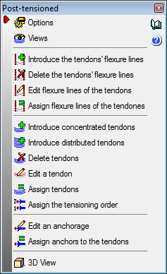
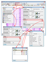
Detailed in the following sections are the options users have available to define the post-tensioned tendons. This options are located in the Post-tensioned dialogue box (Beam Definition tab > Post-tensioned).
Options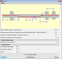
The "Options" dialogue box (Beam Definition tab > Post-tensioned > Options) allow users to configure the options to define the layout of the tendon (initial straight length, distance between contra-flexure points, flat length of the centre span as well as the top and bottom cover of the tendon). In the Tensioning load section of this dialogue box, users can indicate the post-tensioned load percentage, depending on the characteristic yield strength or characteristic resistance, and the losses percentage.
 Views
Views
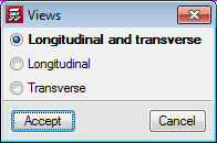
The type of path that is to be displayed (longitudinal, transverse or both) can be selected in the Views dialogue box (Beam Definition tab > Post-tensioned > Views).
Introduce tendon flexure lines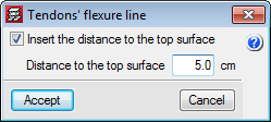
The flexure lines of the tendons are introduced by users. The intersections of the flexure lines with the layouts of the tendons, displayed on the plan view, represent the points where the tendon curves to reach its maximum elevation. They could be defined as virtual frames which support the tendons.
When a flexure line is introduced, a dialogue box appears in which users can activate the option to Insert the distance to the top surface and define its numerical value for the flexure line that is being introduced. The tendons that cross this flexure line will adopt this value as their minimum top cover at that point. If the option to “Insert the distance to the top surface” has not been activated, the value of the cover will be that which has been defined in the Options dialogue box (Beam Definition tab > Post-tensioned > Options) in the parameter: Distance to the top surface in the intermediate supports.
By having the distance between the tendons and the top surface at intermediate supports as an option in the flexure lines box, different top covers can be defined for the same tendon in a more rapid and intuitive manner, which is useful for cantilevers or slabs with varying depthsDelete tendon flexure lines
This option is used to delete flexure lines. Once selected, users mark the flexure lines to be deleted using the left mouse button, followed by a click with the right mouse button to confirm the order.
Edit tendon flexure lines
Allows for a flexure line that has been introduced previously to be edited.
Assign tendon flexure lines
Allows users to select a flexure line and then assign it to others selected individually or using a capture window.
Tendon introduction
The Post-tensioned dialogue box (Beam Definition tab > Post-tensioned) contains two options to introduce the layout of the tendons: Introduce concentrated tendons and Introduce distributed tendons. The difference between these two options lies in the way the number of tendons to provide is defined. The following are defined in both cases:
- Initial anchorage
- Angle with the top surface
- Distance to the top surface
- Selection of active or passive anchor (selected by choosing the corresponding image)
- Final anchorage
- Angle with the top surface
- Distance to the top surface
- Selection of active or passive anchor (selected by choosing the corresponding image)
- Type of tendon
Using the or
or  buttons, users can define:
- Bonded or unbonded tendon
- Number of strands
- Strand area
- Minimum radius of curvature
- Characteristic yield strength
- Characteristic resistance
- Resistance reduction coefficient
- Duct width
- Duct height
- Layout options
- General job parameters
The tendons that are introduced will have the options defined in the options dialogue box (Beam Definition tab > Post-tensioned > Options).
- Particular job parameters
The tendons that are introduced will have specific options which have to be defined upon selecting this option.
Introduce concentrated tendons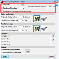
Within the Introduce concentrated tendons dialogue box (Beam Definition tab > Post-tensioned > Introduce concentrated tendons), users indicate (as well as all the options indicated in the previous section: "Tendon introduction") the separation between tendons and either:
- The strip width in which the tendons are going to be placed with the indicated separation (and so, the number of tendons to place is defined).
- The number of tendons that are going to be placed with that separation (and so, the strip width in which the tendons are going to be placed is defined).
Once the dialogue box has been accepted, the layout of the tendons that have been defined is drawn.
Using this option, flexure lines can be included in the direction of the tendons that are being introduced. To do so, the Introduce concentrated tendons dialogue box contains the option to add a flexure line for tendons at right-angles to those being introduced (whereas the Introduce distributed tendons dialogue box does not include this option). If the flexure lines have been defined beforehand (using the Introduce tendon flexure lines option, for example), the option to "Generate tendon flexure lines" must be deactivated, so to not duplicate their introduction.
Introduce distributed tendons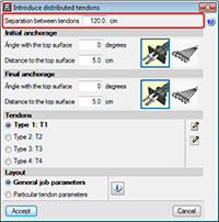
Within the Introduce distributed tendons dialogue box (Beam Definition tab > Post-tensioned > Introduce distributed tendons), users have to indicate (as well as all the options indicated in the "Tendon introduction" section) the separation between tendons. Once the dialogue box has been accepted, the layout of the tendons is defined graphically and the strip width along which they are going to be placed.
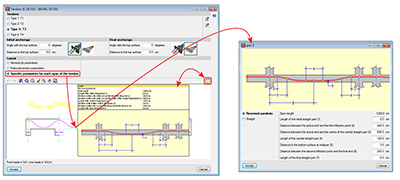
Tendon edition
Using the Edit a tendon option (Beam Definition tab > Post-tensioned > Edit a tendon), one of the introduced tendons can be selected so to modify the layout or type of tendon.
Assign tendons
Using the Assign tendons option (Beam Definition tab > Post-tensioned > Assign tendons), the properties of a tendon can be copied to others. Once the option has been selected, users can mark a tendon (base tendon) using the left mouse button. The tendon edition dialogue box will appear (where the properties of a selected tendon can be modified), and once accepted, the program requests which data is to be copied (Type of tendon, Layout and Tensioning order) to the tendon or tendons which are then selected (multiple selection, or selected one by one). Once the selection has been carried out, users are to click on the right mouse button to validate the assigning of the properties of the base tendon.
Assign the tensioning order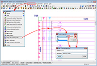
Using the Assign the tensioning order option, users can define, on screen or drawings, the order which is to be followed to tense the tendons.
To do so, users must select a tendon, and create a reference and a description indicating the tensioning order. The tendons which are to be tensioned simultaneously (multiple selection, or selected one by one), and then validate the selection by clicking on the right mouse button.
Edit an anchorage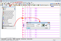
The option Edit an anchorage (Beam Definition tab > Post-tensioned > Edit an anchorage) allows users to modify its type, angle or distance from the top surface.
Assign anchors to the tendons
Using the option: Assign anchors to the tendons (Beam Definition tab > Post-tensioned > Assign anchors to the tendons), users can copy the properties of an anchorage to others. Once the option has been selected, users can mark an anchor (base anchor) using the left mouse button. The anchorage edition dialogue box will appear (where the properties of a selected anchorage can be modified), and once accepted, the program requests which data is to be copied (Type of anchorage, Angle with the top surface and Distance to the top surface) to the anchor or anchors which are then selected (multiple selection, or selected one by one). Once the selection has been carried out, users are to click on the right mouse button to validate the assigning of the properties of the base anchor.
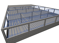
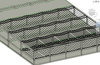
3D view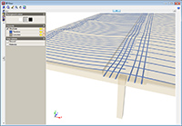
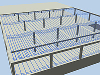
Using the 3D View option (Beam Definition tab > Post-tensioned > 3D View), the program displays a 3D view of the current floor with the layout of the tendons.
On-plan representation of the deviation loads of the post-tensioned tendons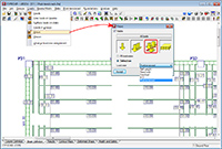
Due to the parabolic layout of the tendon, pressure forces arise which push toward the inside of its curvature. The program will automatically generate these forces in each of the tendons, which do not display any layout errors (tendons with layout errors, will be shown marked with a red circle).
To view the deviation loads of the tendons on screen, a button has been implemented: “View loads of the post-tensioned tendons” in the dialogue box where the visibility options of the loads of the job are configured (Loads > Views). This button is not activated by default, as the number of loads that can be represented in a post-tensioned slab can make the viewing of other elements difficult and would also slow down the drawing of image of the floor.
Post-tensioned slab reports
The program generates reports with the properties of the post-tensioned data introduced by users and the data analysed for each floor group in which post-tensioned tendons have been introduced (File > Print > Job report):
- Materials
- Unbonded tendons
- Bonded tendons
- Tendon description
- Deviation loads
- Take-off
- Strands
- Active anchors
- Passive anchors
- Unbonded tendon ducts
- Bonded tendon ducts
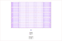
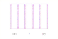
Post-tensioned slab drawings
Post-tensioned drawings have been implemented to the existing list of drawing types, (File > Print > Job drawings). The program generates two drawings for each floor group containing post-tensioned tendons; one for longitudinal tendons and another for transverse tendons. The drawings display the layout of the tendons on plan, and indicate, per metre, the distance of the tendon to the base of the slab at that point.
Export to IFC of the tendons of post-tensioned concrete slabs
CYPECAD includes the export to IFC format (Industry Foundation Classes) of the tendons of the post-tensioned slabs (File > Export > IFC).
Properties of the analysis of the post-tensioned slabs carried out by CYPECAD
The Post-tensioned slabs for building module, considers both bonded tendon and unbonded tendon technology, whose field of application is for use with the usual building specifications and for loads and spans normally applied for residential buildings, offices and business premises.
In the case of unbonded tendons, the prestressing action is taken directly via the actions at the ends of the tendons and the deviation forces, and so the program directly considers the action when designing the passive reinforcement. For adherent tendons, the contribution of the remaining capacity of the active reinforcement will also be taken into account, deducting it to establish the passive reinforcement.
The effects of any compression or possible shortening of the reinforcement is not taken into account, nor the retaining effect of the supports, as the slabs maintain their rigid diaphragm hypothesis, when obtaining forces, designing or checking the tendons for compression, tension and cracking.
By not taking into account the compression forces of the tendons, an extra safety factor is being applied, as their effect is usually favourable. The effect any on-plan shortening of the slab may have due to forces introduced by the tendons, is also ignored. This influence is minimal and may even benefit the design of the supports, as long as their stiffness and distribution favour this effect.
Users are to choose whether the additional effects of the compression forces, shortening and forces induced on the other structural elements, which are not taken into account by CYPE, are to be considered in the design, be it because of the spans, loads, distribution of the supports, their stiffness or any other particular aspects of the building.
The general data that is requested generally covers all the technology that is present in the market. Users are to provide the data concerning the yield strength and resistance of the steel, the loss due to all concepts, so to estimate the load applied to the tendons, and the layout of the cables to establish the deviation forces to apply to the slab in the post-tensioning loadcase.
Post-tensioned slabs also provide benefits such as reduction in cracking, an increase in bending moment, shear and punching shear resistance, reduction of the depth and deflection of the slabs, and therefore CO2 emissions. The main disadvantages include having to control the cover and any possible unforeseen intersecting of the tendons, differed deformation, on-plan shortening and retention caused by the supports, depending on their stiffness, distribution and order of the construction process.
The average compression forces in post-tensioned slabs for buildings, usually lie in the range of 0.8 MPa to 3.5 MPa, to control cracking and limit shortening.
The ACI code establishes an average compression force in post-tensioned slabs for buildings of 0.9 MPa and a maximum tendon separation of one and a half metres or eight times the thickness of the slab, in at least one direction, which as well as controlling cracking, prevents failure due to punching shear.
It is recommended the design proposals of each code be applied and to bear in mind the compression and tension limitations of the end fibres of the sections established by each code, because, as was said earlier, this check is not carried out by the present module.
Permits required
For CYPECAD to be able to carry out the design of the post-tensioned slab as described on this page, the user license must include the Post-tensioned slabs for buildings module
CYPECAD versions
CYPECAD is available in its unlimited version and also in two limited versions called LT30 and LT50, which contain the same tools and module acquisition possibilities, but have the following conditions:
CYPECAD LT50:
- Fifty columns
- Four floor groups (Floor group: floors which are the same and consecutive)
- Total of five floors
- Walls: one hundred linear metres
CYPECAD LT30:
- Thirty columns
- Four floor groups (Floor group: floors which are the same and consecutive)
- Total of five floors
- Walls: one hundred linear metres
Integrated 3D structures of CYPECAD (also LT50 and LT30) is not technically a module. To define these 3D structures in CYPECAD, users must also have the required permits to use CYPE 3D in their user license and, optionally, modules which are exclusive to CYPE 3D.
CYPECAD Modules
The following modules are those that can be acquired together with CYPECAD or CYPECAD LT:
- Steel columns
- Steel beams
- Joist floor slabs (generic concrete joists)
- Joist floor slabs (in-situ, precast and steel)
- Timber joist floor slabs
- Waffle slabs
- Flat slabs
- Punching shear verification (Also operates as an independent program)
- Composite slabs
- Hollow core slabs
- Post-tensioned concrete slabs for buildings
- Shear walls
- Reinforced concrete walls
- Plane stress walls
- Stairs
- Mat foundations and foundation beams
- Concrete block walls
- Interaction of the structure with the construction elements
- Automatic job introduction: DXF, DWG and CAD/BIM models
- Collective protection systems
Modules common to CYPECAD and CYPE 3D:
- Concrete columns
- Composite steel and concrete columns
- Concrete beams
- Timber sections
- Pile caps (includes strap and tie beams)
- Baseplates
- Footings (pad and strip) (includes strap and tie beams)
- Advanced design of surface foundations
- Fire resistance check
- Parallel analysis with two multiprocessors
- Parallel analysis with up to eight processors
- Joints I. Welded. Warehouses with rolled and welded steel I sections
- Joints II. Bolted. Warehouses with rolled and welded steel I sections
- Joints III. Welded. Building frames with rolled and welded steel I sections
- Joints IV. Bolted. Building frames with rolled and welded steel I sections
- Joints V. Flat trusses with hollow structural sections
- Export to Tekla
Tel. USA (+1) 202 569 8902 // UK (+44) 20 3608 1448 // Spain (+34) 965 922 550 - Fax (+34) 965 124 950